Category Archives: ESP32

ESP32 with 6V-35V Switching Regulator

I have had several request for an ESP32 board with an input voltage range suitable for operating off a 12V battery or a solar panel and battery. I added a switching regulator to the base ESP32 development board. The board is the same size as my popular ESP32 board and can work with an input voltage in the 6V to 38V range. The board can be powered directly from automotive power without additional spike suppression. That makes the board suitable for use in RVs, cars and motorcycles without external regulators. In addition to powering itself the board can power some external devices with 5V up to 200mA while powering the ESP32. The board can be powered from an external power supply of up to 38V or the USB connector or both at the same time.

Using an ESP32 in a vehicle has required a separate power supply that can survive the spikes present on the power due to the starter motor and ignition noise. A power supply with an 18V input does not survive in an automobile, the spike kill it. The design I used on this board has been extensively used in designs fitted in cars and it is reliable.

The design and layout of the switch mode regulator does not limit the sensitivity of the ESP32 to WiFi or Bluetooth signals.

The switching regulator can provide 5V at 500mA continuously and I recommend that the external current draw be limited to 200mA. An ESP32 does not need a 300mA supply but I have found that if I have a load of greater than 250mA on the external 5V pin then sometimes the ESP32 does not power up correctly.

One of the applications of this board is to drive a Nextion intelligent display with the ESP32. I have tested the board with displays up to 3.5″ and they work correctly when powered off the 5V output from the ESP32_SW board. Nextion provides a 3D printable bezel for the displays and its easy to add a back cover to house the ESP32 in the same enclosure.

The switching regulator is not super low power when it is unloaded. The current draw from the high voltage input is in the order on 1mA average if the ESP32 is in sleep mode. While not in the micro-amp range of the ESP32 with a good LDO it is low enough because of the huge capacity of most 12V batteries to not present a significant load on the battery.

ESP32 with Switch Mode Regulator.

https://www.ezsbc.com/index.php/products/wifi01-sw.html

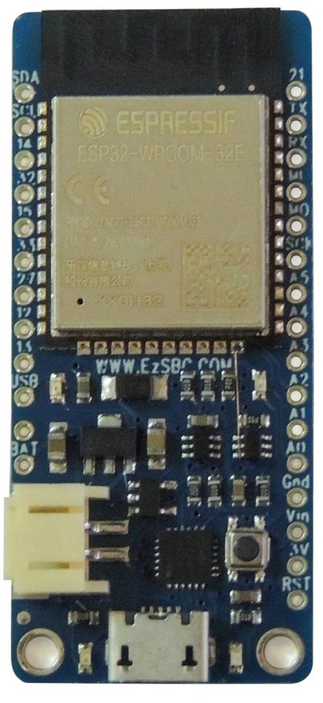
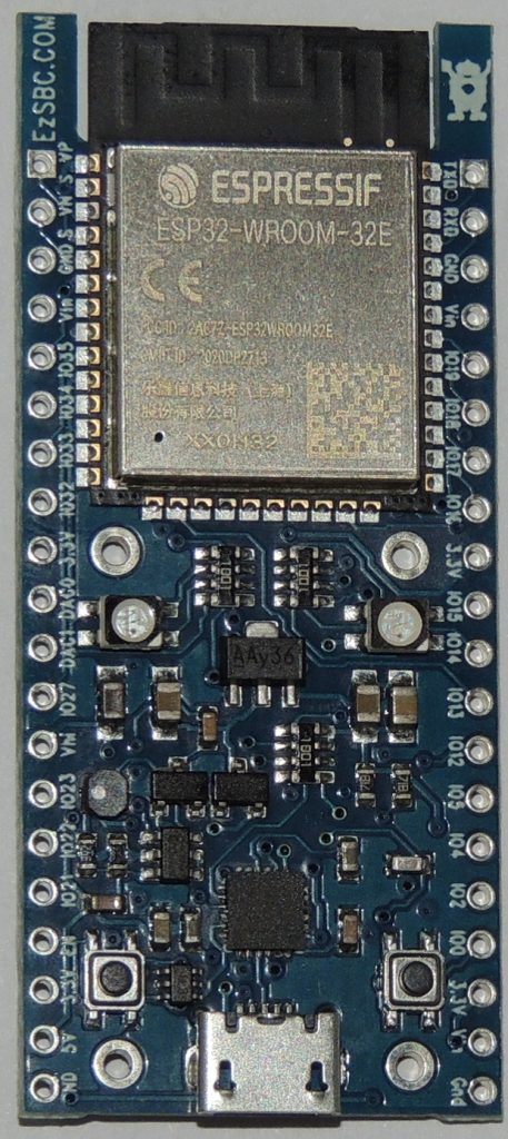
Please note that the high voltage input is labeled Vhi. The Vin pins are the same pins as on the other modules with the same form factor and is the voltage at the input of the LDO.

ESP32 In Feather Format

In the store you can find an ESP32 board with the PCB outline and pinout of a Huzzah32. Normally my designs are original and try to maximize the functions that are available on the board pins. This board breaks with the tradition and is a clone of an existing design.

Why make a clone of another board? First and foremost it is not a straight copy of he original board, rather it is an improved version of the Huzzah32. The original has issues with the biggest two being the price and the power consumption in deep sleep mode. The current consumption in deep sleep mode is about 10uA. The battery voltage monitor is nearly identical to the original and has two 100k resistors in series with the center tap connected an ADC channel . In this design it would be the dominant power draw in Deep Sleep mode so I added a high side switch that disconnects the resistors from the LiPo-cell when the board is in sleep mode.

Other small changes are the addition of activity LEDs for the RX and TX signals of the USB to Serial converter, a cutout of the PCB underneath the printed antenna of the Wroom-32 module to restore the RF performance of the Wroom-32 module.

https://www.ezsbc.com/index.php/products/esp32-feather.html

Cell Voltage Measurement

There’s an extra step needed measure the cell voltage. By default the sense resistors are not attached to the cell since they would represent a constant current drain of about 20uA on the charged cell. The original Huzzah 32 design has such terrible deep sleep current consumption that the extra 20uA was not a big deal compared the the 2mA static load on the cell.

To turn on the voltage sensing IO-pin 2 has to be set high before the voltage is measured. After the voltage measurement IO-2 should be set low to conserve battery charge. When the ESP32 is put into deep sleep mode IO2 is automatically low so that the resistors are disconnected.

ESP32 Analog Input – analogRead

AnalogRead does indeed work on the ESP32.  Many sites and posts that claim that the Analog to Digital converter of the ESP32 doesn’t work.  I have tested analogRead using the code below and it works as expected.  The code below compiles and downloads to my ESP32 Development board and produces correct results.  The input pin is the seventh pin from the top on the left hand side of the ESP32 Development Board.

#define RLED 16
#define InPin 33

int x ;

void setup() {
   Serial.begin(115200);
   pinMode(RLED, OUTPUT);
}

void loop()
{
   digitalWrite(RLED, LOW);
   delay(100);
   x = analogRead( InPin );
   Serial.println( x );
   digitalWrite(RLED, HIGH);
   delay(100);
}

Have fun!

ESP32 Board Selection in Arduino

I receive many questions in a week on the correct setup of the Arduino Environment to program the ESP32 development board.   At this point it doesn’t seem to matter which board you select and I always use “Esp32 Dev Module” as my selection.  The rest of the setting can be seen in the screen capture below.

ESP32 Arduino Setup

ESP32 Arduino Setup

The upload speed is fast and it works just like an Arduino board.  Press the upload button and the code magically appears in the module memory.  No buttons to press, just works.

ESP32 Development Board-Again Part 2

If you compare the first revision of the ESP32 Development board to the current version you will see that the ESP32 module doesn’t extend past the edge of the printed circuit board as it did before.  I extended the PCB and had the area under the antenna routed out.  This serves two purposes.  The ESP32 module is designed to have the antenna sit out in free space.  The antenna is not supposed to sit on top of the PCB, the design guide by Espressif makes that very clear.  The measurements that they did and documented show clearly that there is a significant loss in performance when the antenna sits on top of the PCB.  The module’s PCB is much thinner than the standard 1.6mm PCB and they obviously designed the antenna for the thin pcb.  User reviews of some of the other ESP32 boards on the market confirm that the ones where the module sits completely on top of the PCB have poor RF performance.

The second purpose of having the PCB extend all the way to the top of the module’s  PCB is to allow me to manufacture the boards in a panel.  If the module extends past the PCB then you can only place them next to each other in the panel.  This leads to a long and narrow panel which bends in the reflow oven preventing the modules from sitting flush with the PCB.  I ended up breaking the panels in half to get a less flexible panel.  An additional benefit is that the thicker PCB protect the module’s PCB during shipping.