Monthly Archives: March 2017

ESP32 Analog Input – analogRead

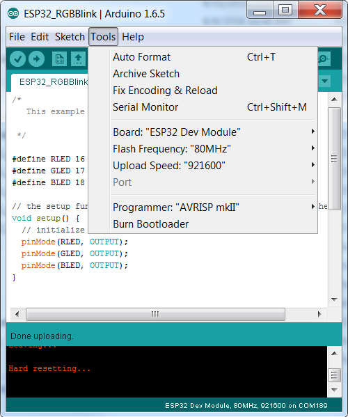
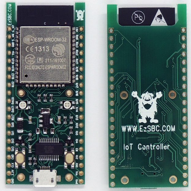
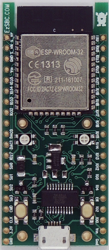
AnalogRead does indeed work on the ESP32.  Many sites and posts that claim that the Analog to Digital converter of the ESP32 doesn’t work.  I have tested analogRead using the code below and it works as expected.  The code below compiles and downloads to my ESP32 Development board and produces correct results.  The input pin is the seventh pin from the top on the left hand side of the ESP32 Development Board.

#define RLED 16
#define InPin 33

int x ;

void setup() {
   Serial.begin(115200);
   pinMode(RLED, OUTPUT);
}

void loop()
{
   digitalWrite(RLED, LOW);
   delay(100);
   x = analogRead( InPin );
   Serial.println( x );
   digitalWrite(RLED, HIGH);
   delay(100);
}

Have fun!

ESP32 Board Selection in Arduino

I receive many questions in a week on the correct setup of the Arduino Environment to program the ESP32 development board.   At this point it doesn’t seem to matter which board you select and I always use “Esp32 Dev Module” as my selection.  The rest of the setting can be seen in the screen capture below.

ESP32 Arduino Setup

ESP32 Arduino Setup

The upload speed is fast and it works just like an Arduino board.  Press the upload button and the code magically appears in the module memory.  No buttons to press, just works.

ESP32 Development Board-Again Part 2

If you compare the first revision of the ESP32 Development board to the current version you will see that the ESP32 module doesn’t extend past the edge of the printed circuit board as it did before.  I extended the PCB and had the area under the antenna routed out.  This serves two purposes.  The ESP32 module is designed to have the antenna sit out in free space.  The antenna is not supposed to sit on top of the PCB, the design guide by Espressif makes that very clear.  The measurements that they did and documented show clearly that there is a significant loss in performance when the antenna sits on top of the PCB.  The module’s PCB is much thinner than the standard 1.6mm PCB and they obviously designed the antenna for the thin pcb.  User reviews of some of the other ESP32 boards on the market confirm that the ones where the module sits completely on top of the PCB have poor RF performance.

The second purpose of having the PCB extend all the way to the top of the module’s  PCB is to allow me to manufacture the boards in a panel.  If the module extends past the PCB then you can only place them next to each other in the panel.  This leads to a long and narrow panel which bends in the reflow oven preventing the modules from sitting flush with the PCB.  I ended up breaking the panels in half to get a less flexible panel.  An additional benefit is that the thicker PCB protect the module’s PCB during shipping.

ESP32 Development Board-Again

Here is the current version of the$16.95  ESP32 development board using an ESP-WROOM-32 module directly from Espressif.   My optimism about the availability of the ESP32S modules from AI-Thinker was misplaced.  I believe they are finally shipping now but since I haven’t seen any with my own eyes I remain unconvinced.  In the meantime, I switched to a module that is actually available in production quantities.

Top View of New PCB

The ESP32 board has a Espressif WROOM-32 module installed with the pinout marked on the PCB albeit in very small letters.    The PCB is routed out under the antenna for the best RF performance.  The WROOM-32 module is certified worldwide by the relevant authorities and has an FCC Id number.

http://www.ezsbc.com/index.php/products/wifi01-28.html is where you can buy some for $16.95 each.  The schematic is also available for download and there are a few example programs on the forum.